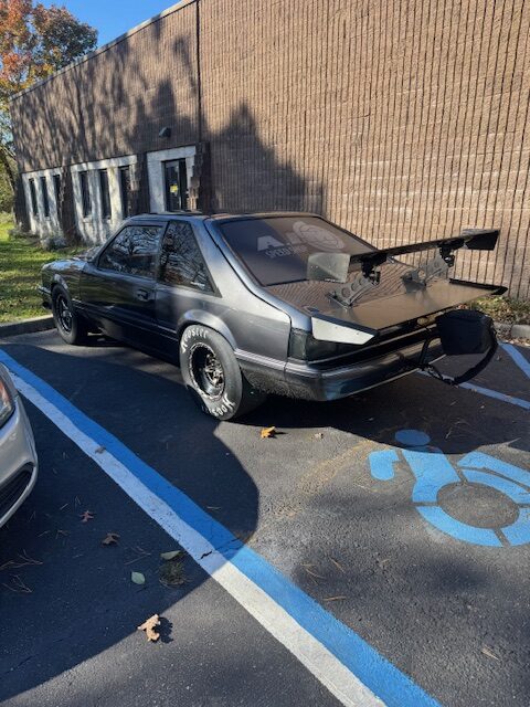
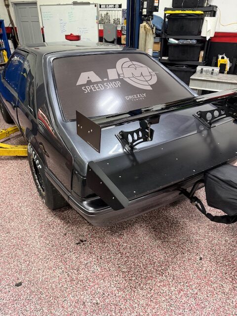
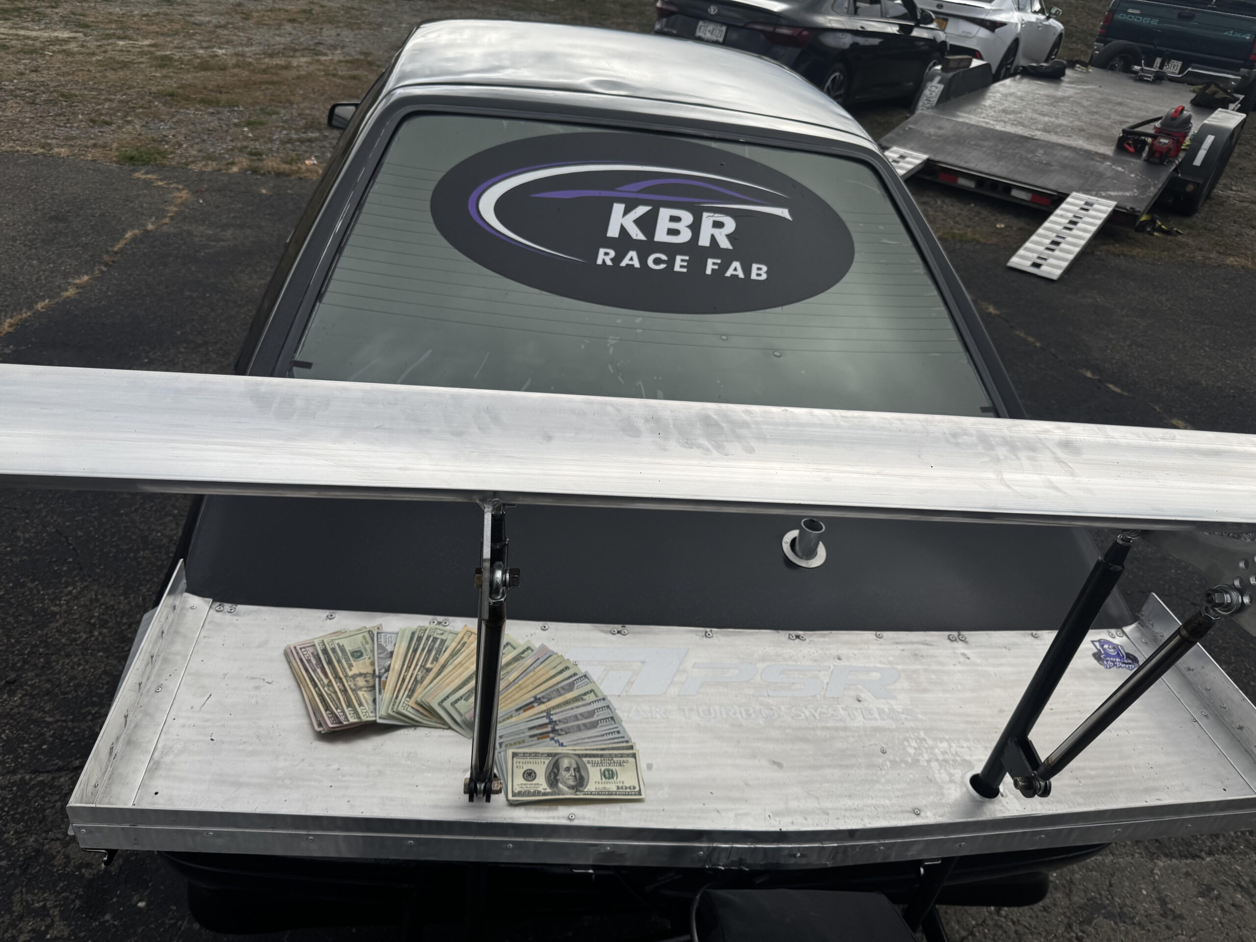
No Prep Racing Wings
No Prep Racing Wing
No Prep Racing Wing
No Prep Racing Wing
No Prep Racing Wing
No Prep Racing Wing
No Prep Racing Wing

No Prep Racing Wing
No Prep Racing Wing
No Prep Racing Wing
No Prep Racing Wing
No Prep Racing Wing
No Prep Racing Wing
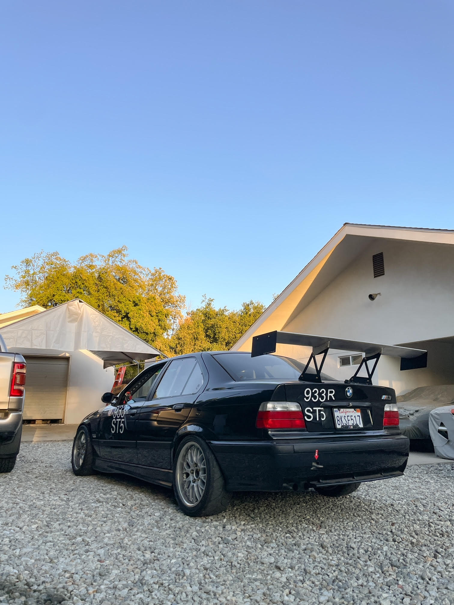
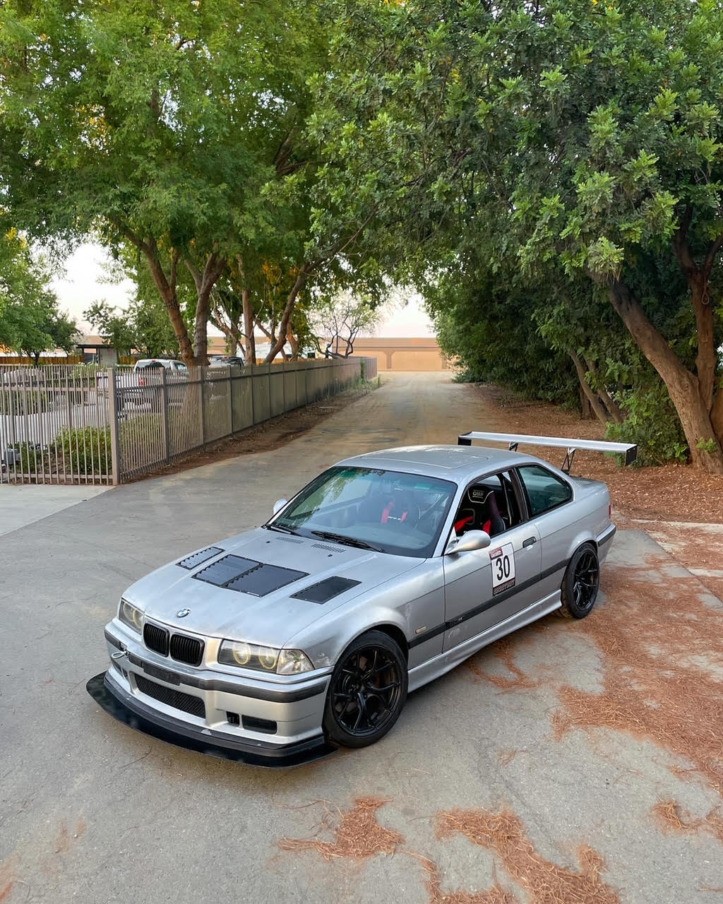
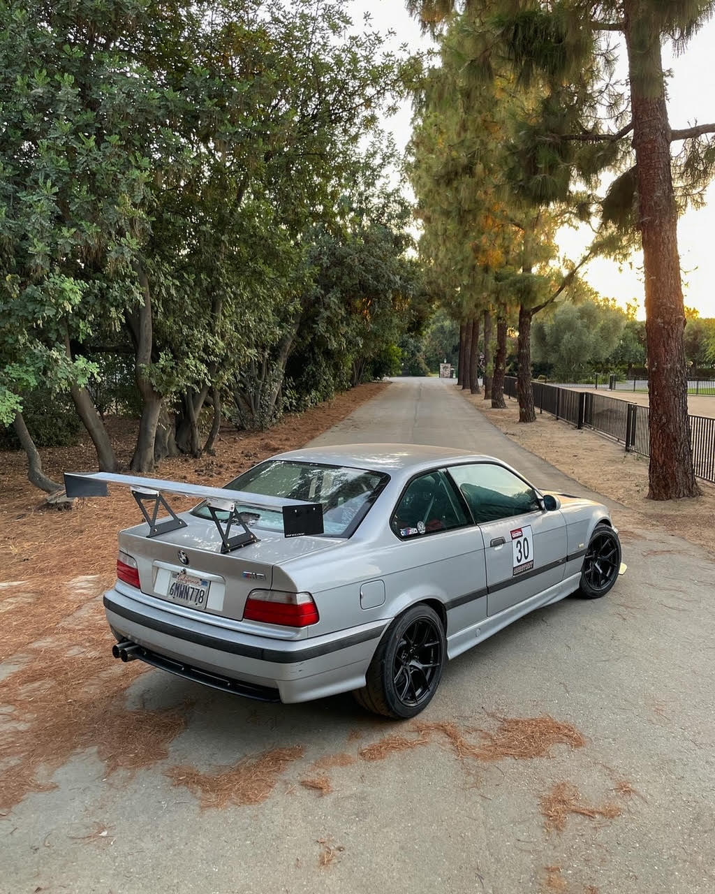
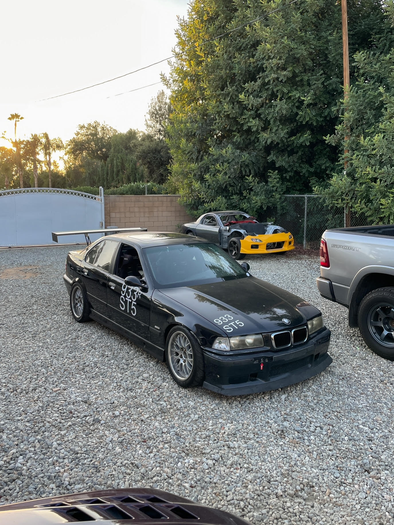
Road Course / Autocross / Time Attack Wings

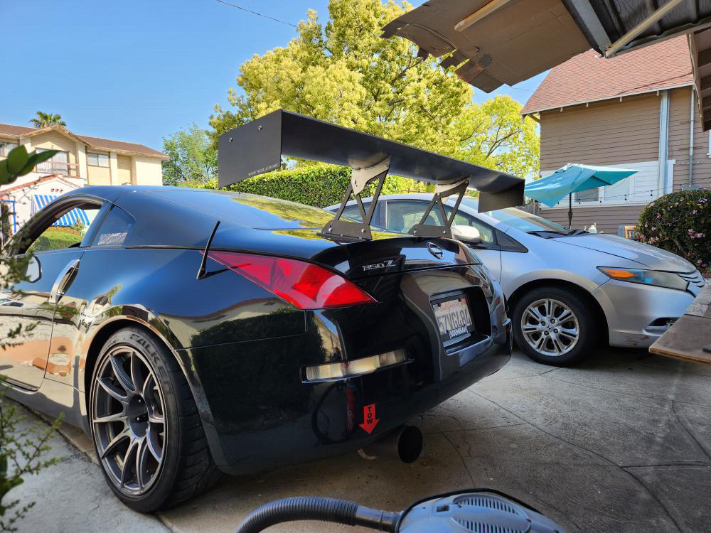


Rear wing
Car racing rear wings

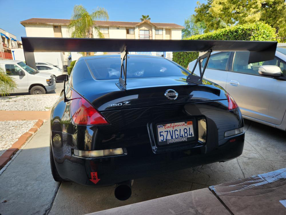
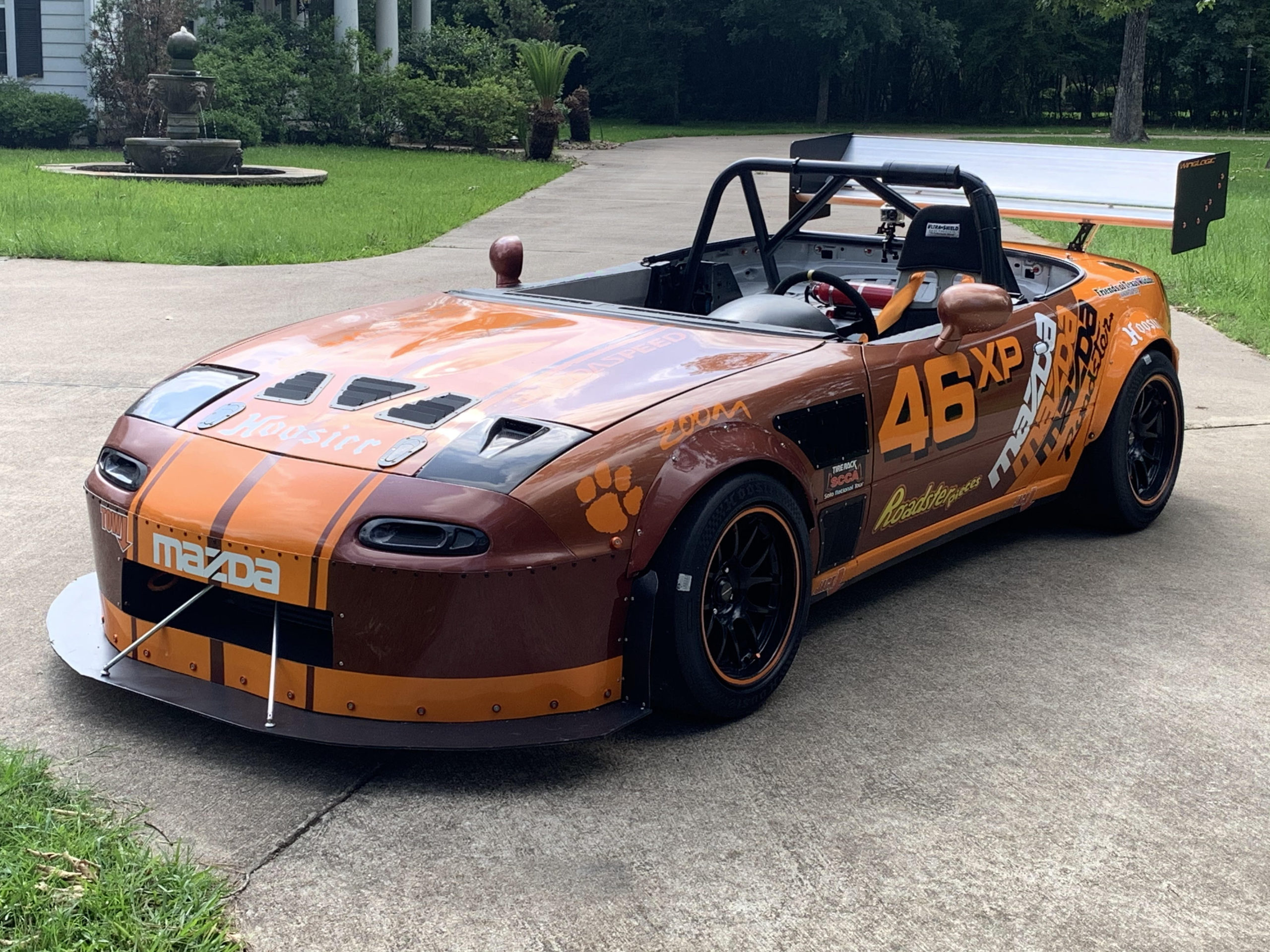
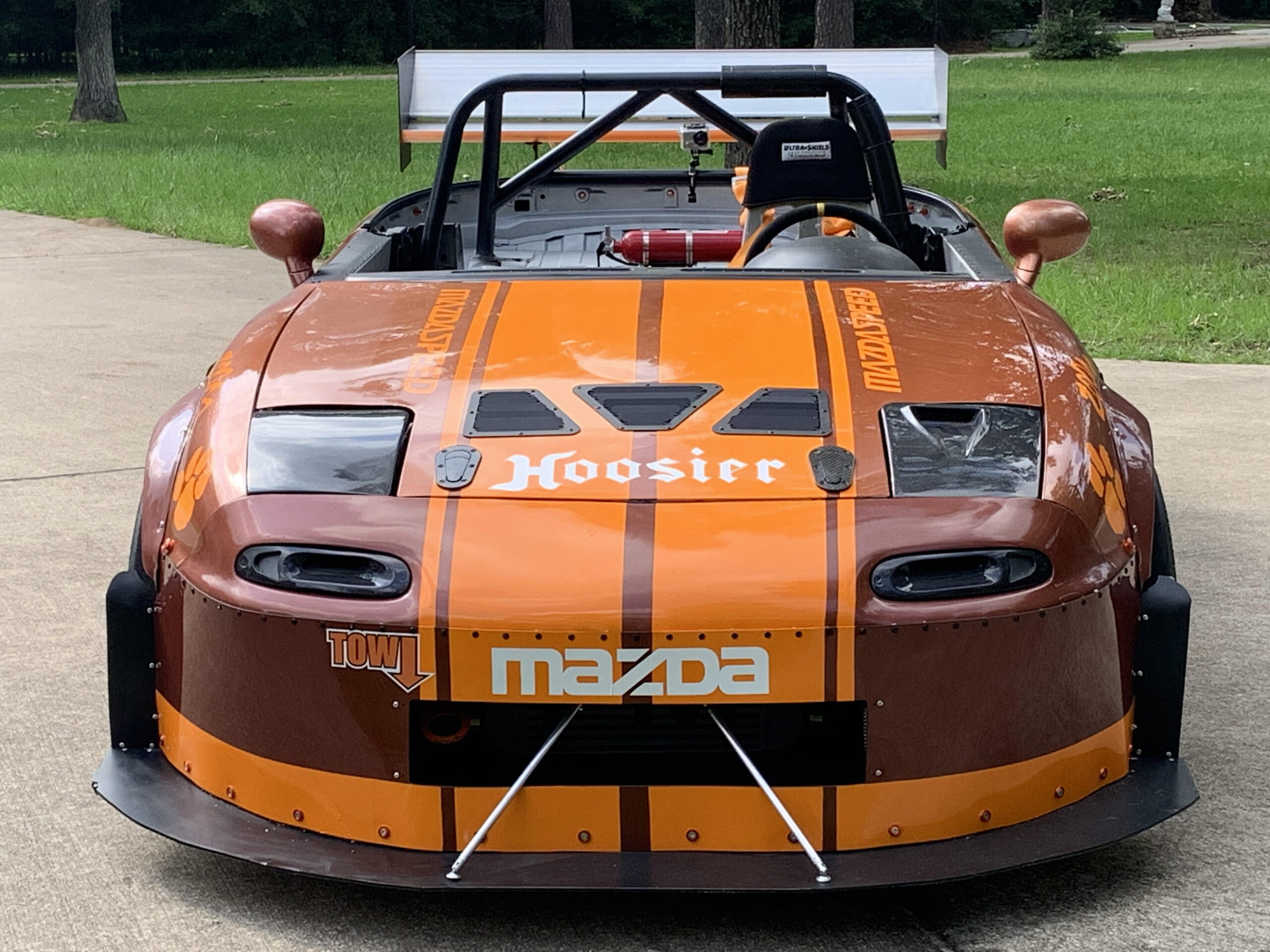
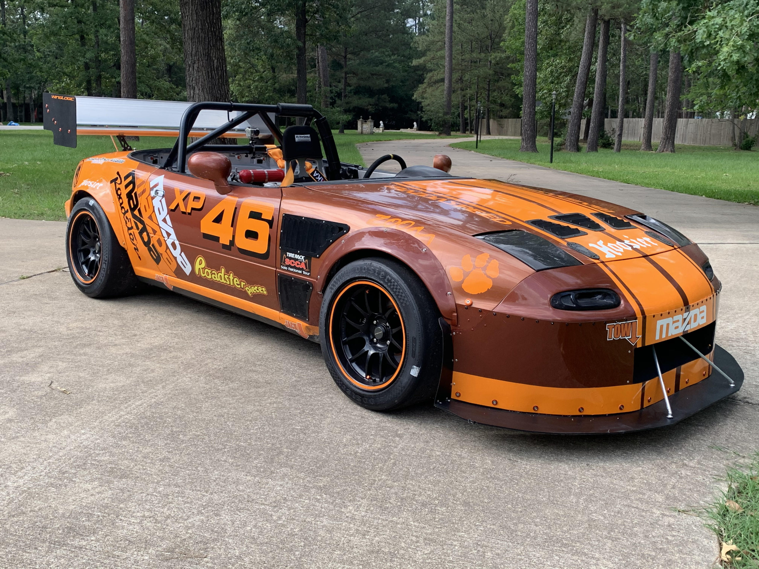
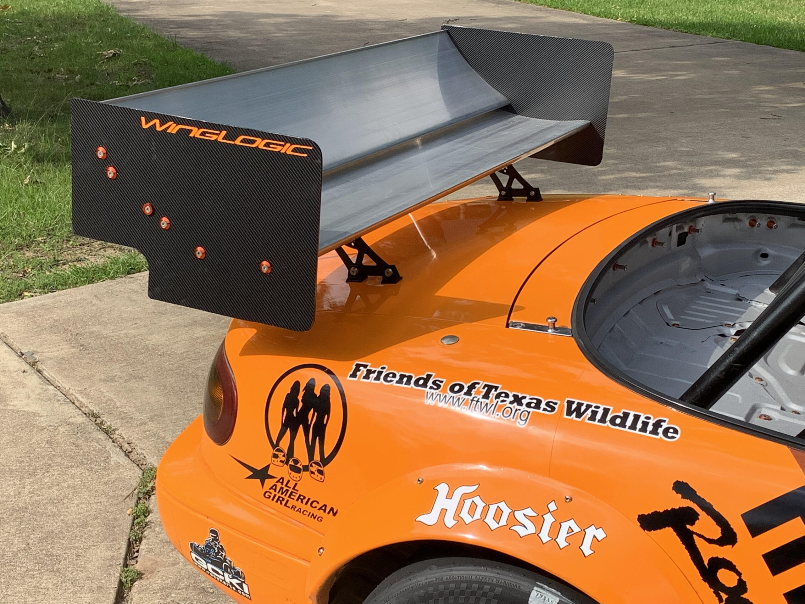
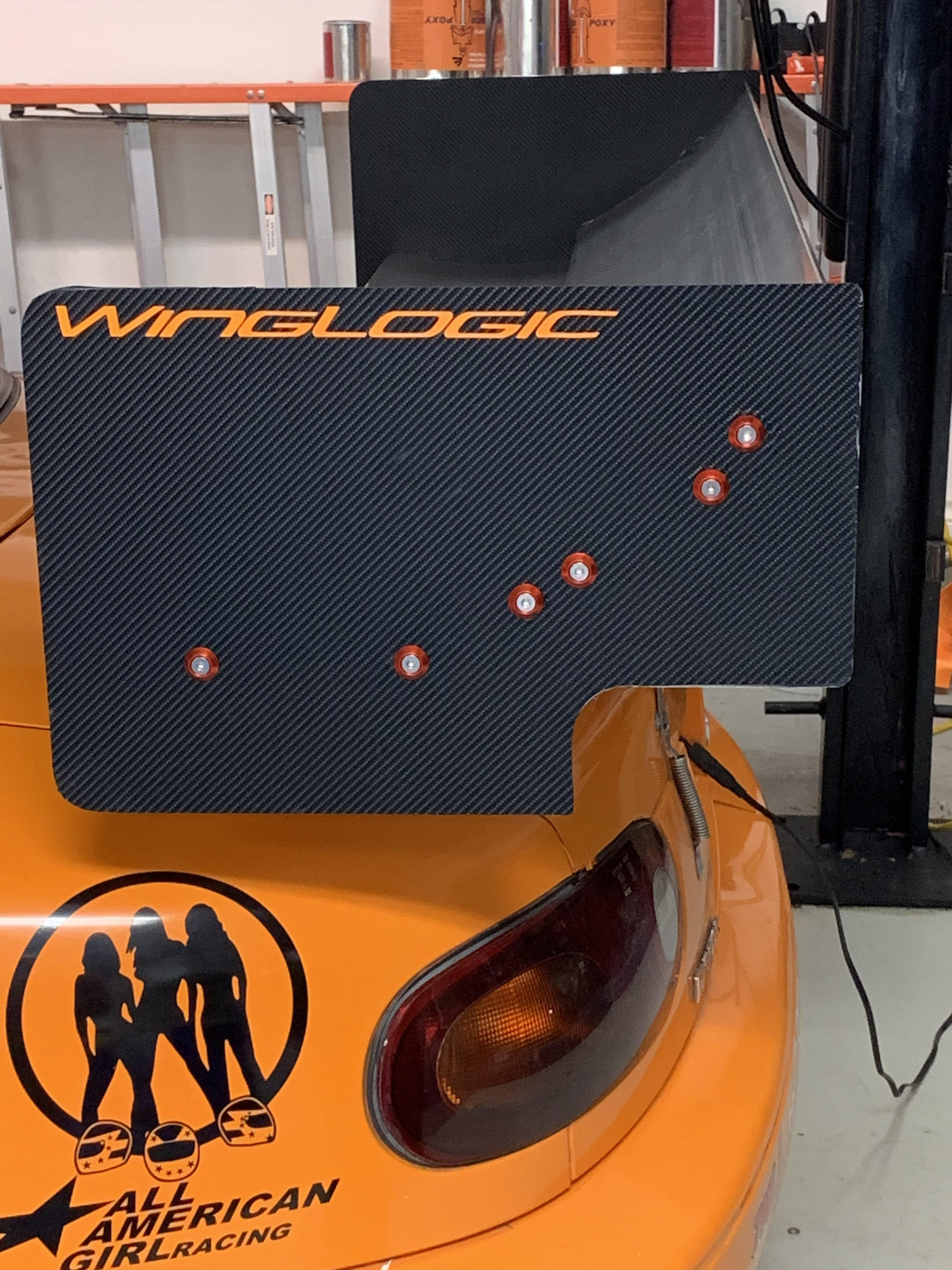
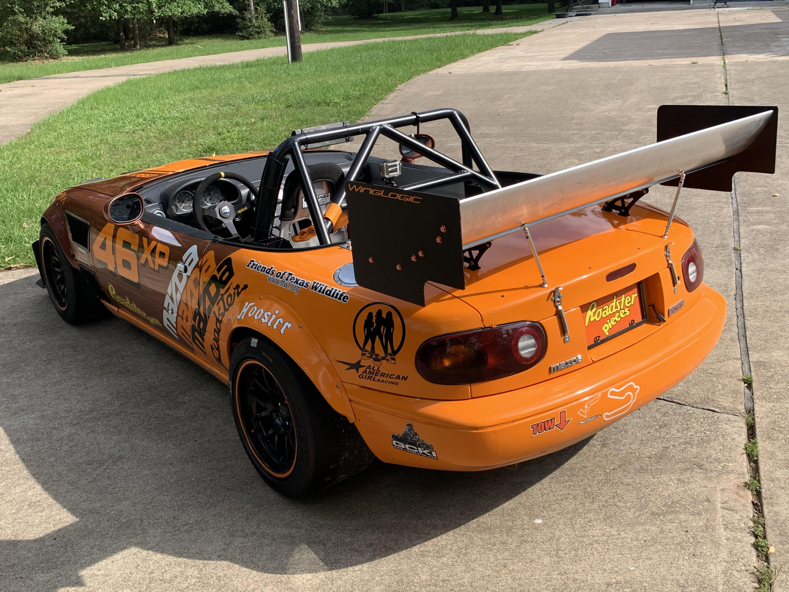
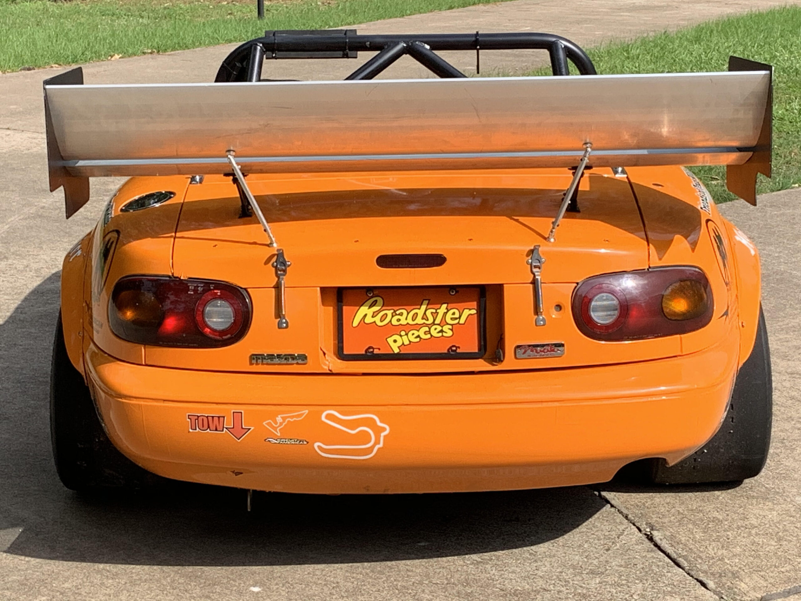
John Bartos – Magnolia, TX – SCCA XP
“The parameters I had to fit to be exactly within SCCA XP guidelines were:
Maximum combined wing surface area (cord x length) 8 square feet
Maximum end plate area 200 sq-inches
Maximum height of wing above highest point on rear deck = 12″
Wing could not extend beyond furthest portion of rear bodywork”
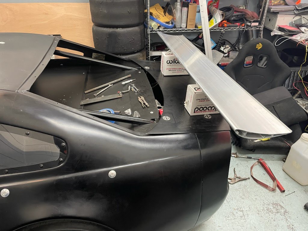
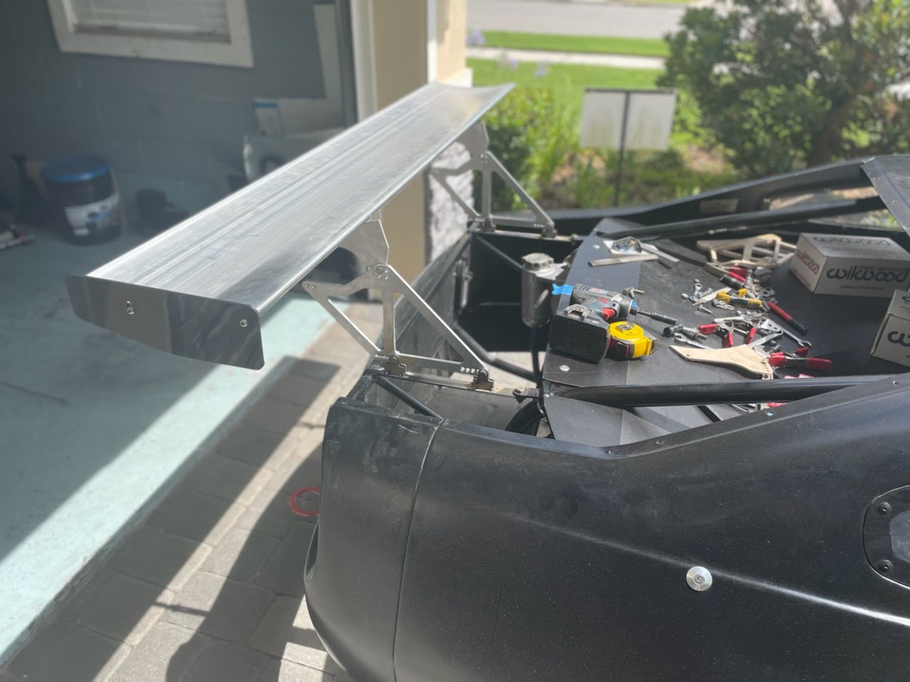
Nick Eley – Orlando, FL
Work in progress


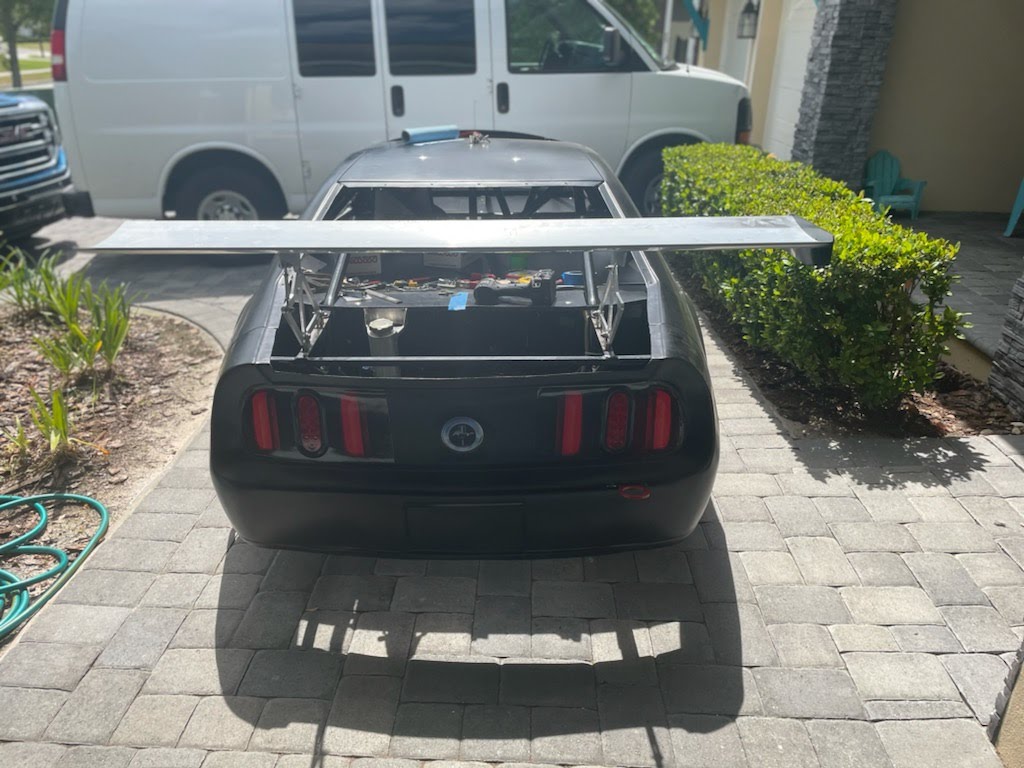


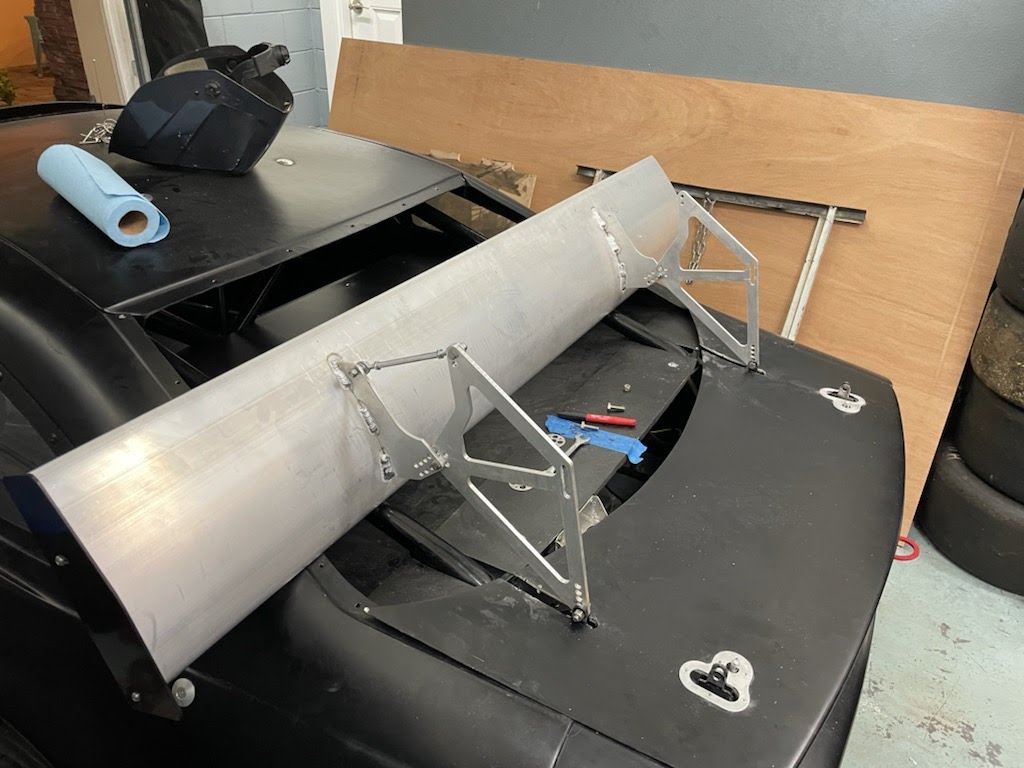
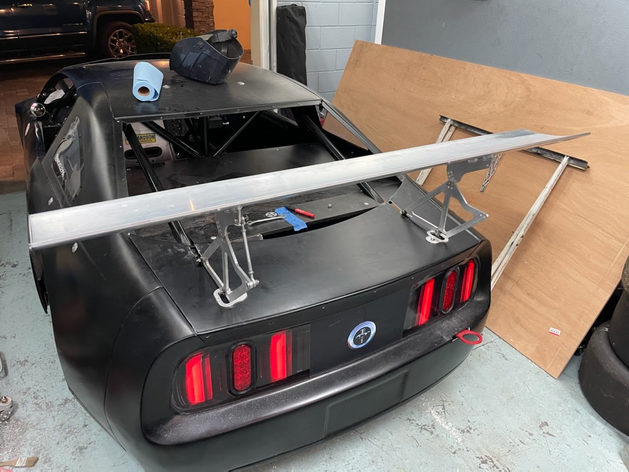
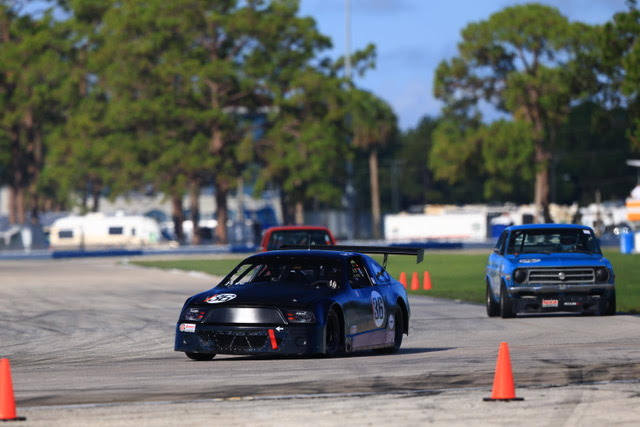
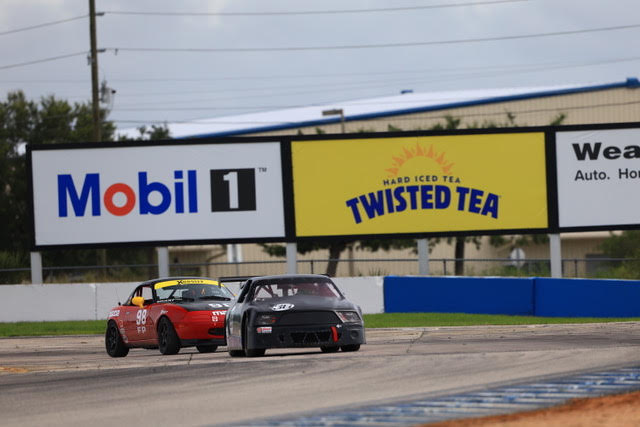
Bert Guynes – Conroe, TX – SCCA XS-B
Parameters to fit within SCCA XS-B guidelines were:
Maximum combined wing surface area (cord x length) 8 square feet
Attachment points must be behind rear axle and not connected to suspension points
Maximum height of wing above highest point of car will be no more than 6”
Wing could not extend beyond furthest portion of rear bodywork
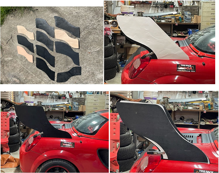
I am trying to build a small Time Attack, Time Trial, Time Sprint car which I will also autocross
some as well.
The car is a 2001 Toyota MR2 Spyder soft top

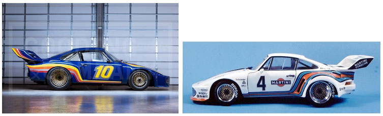
I pulled the original idea for the wing from the old Porsche 935, but with the rules stating the
wing can not extend beyond the end of the car, it limited the design.
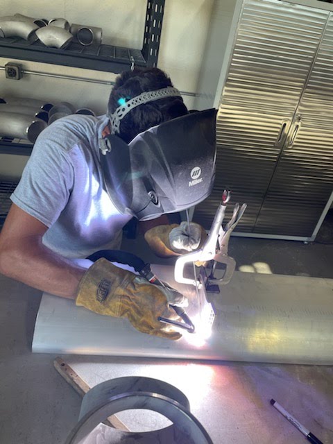
Using a Plasma cutter, I cut a base plate out of 1/8” steel plate, making sure to cut around the
suspension bolt area and bend it to match the frame. Unseen in the picture, I welded another
piece of plate downward to be able to bolt parallel to the suspension coil-over and the thickest
part of the frame. The single bolt in the picture goes through the square tubing of the cross-
member frame. All together there are 7 bolt points holding the upright to the frame of the car.
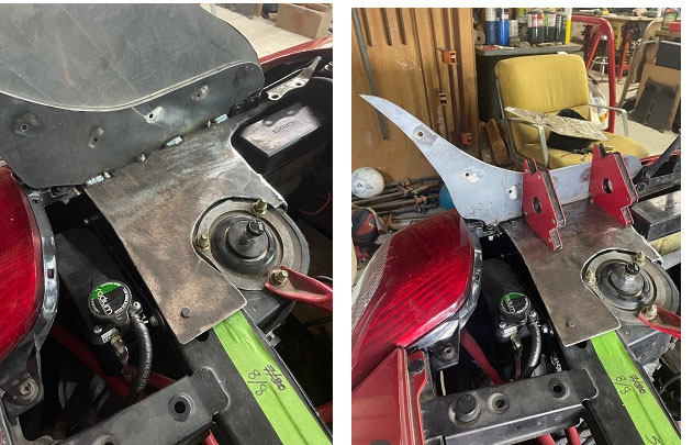
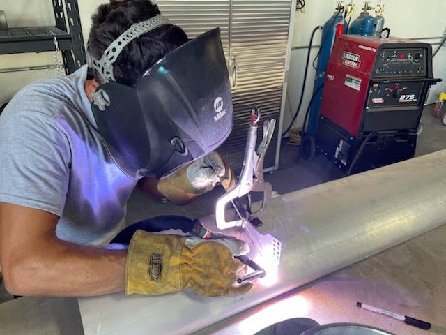
Using a plasma cutter, I cut the upright frame out of the same 1/8” plate. I wanted to
sandwich the aluminum end plate between the 2 uprights to get as ridge as possible, with all
the downforce directly on the rear frame of the car. Once welded together, I mounted the 2
base pieces to the frame using the fender holes, and 4 more points making the entire frame
ridge.

I was able to track down a hardtop, which was the key to the aerodynamic package I wanted
to design and develop.

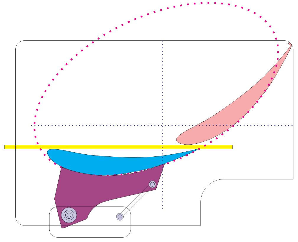
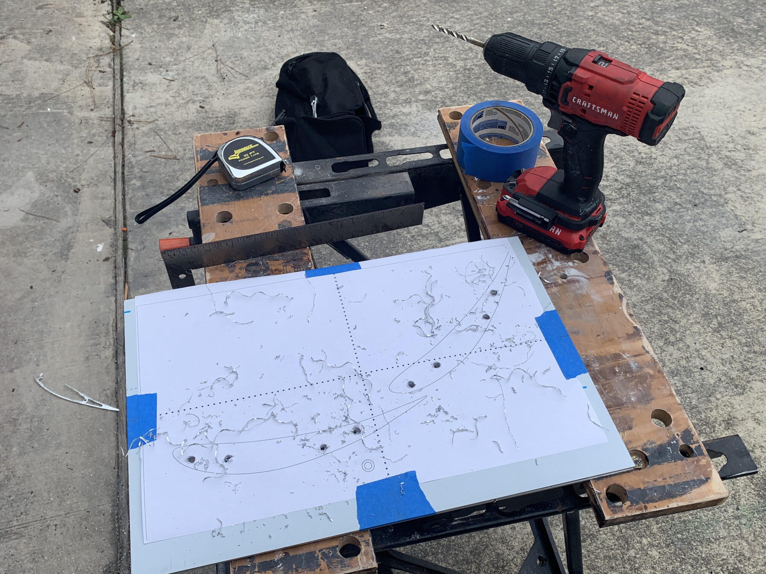
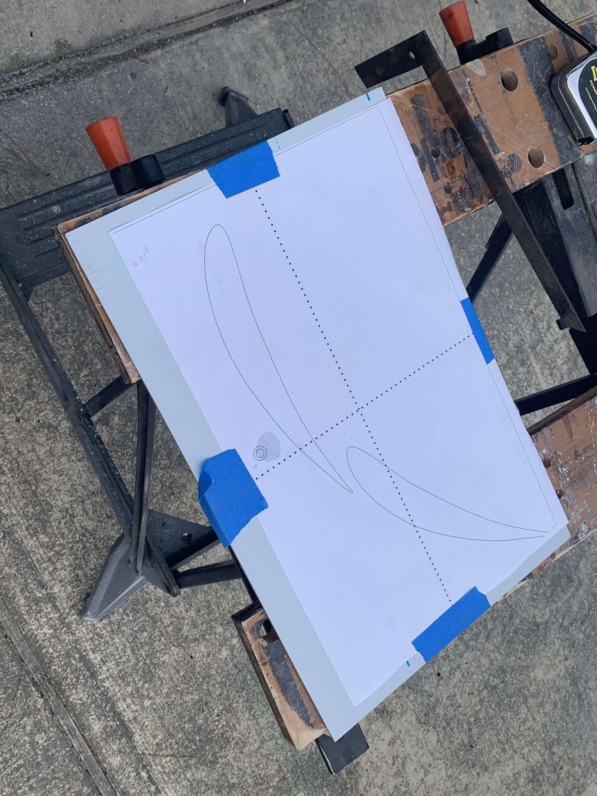
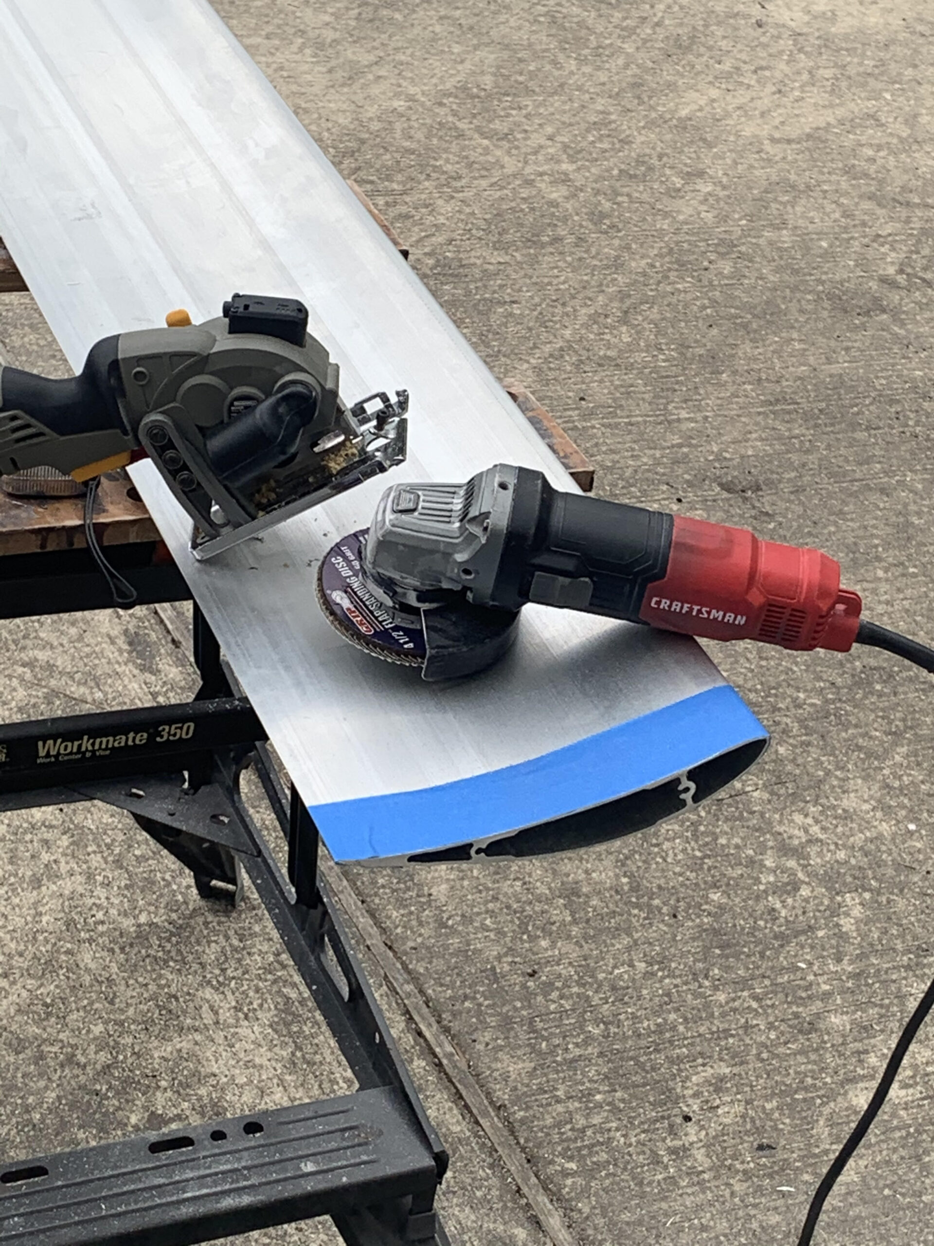
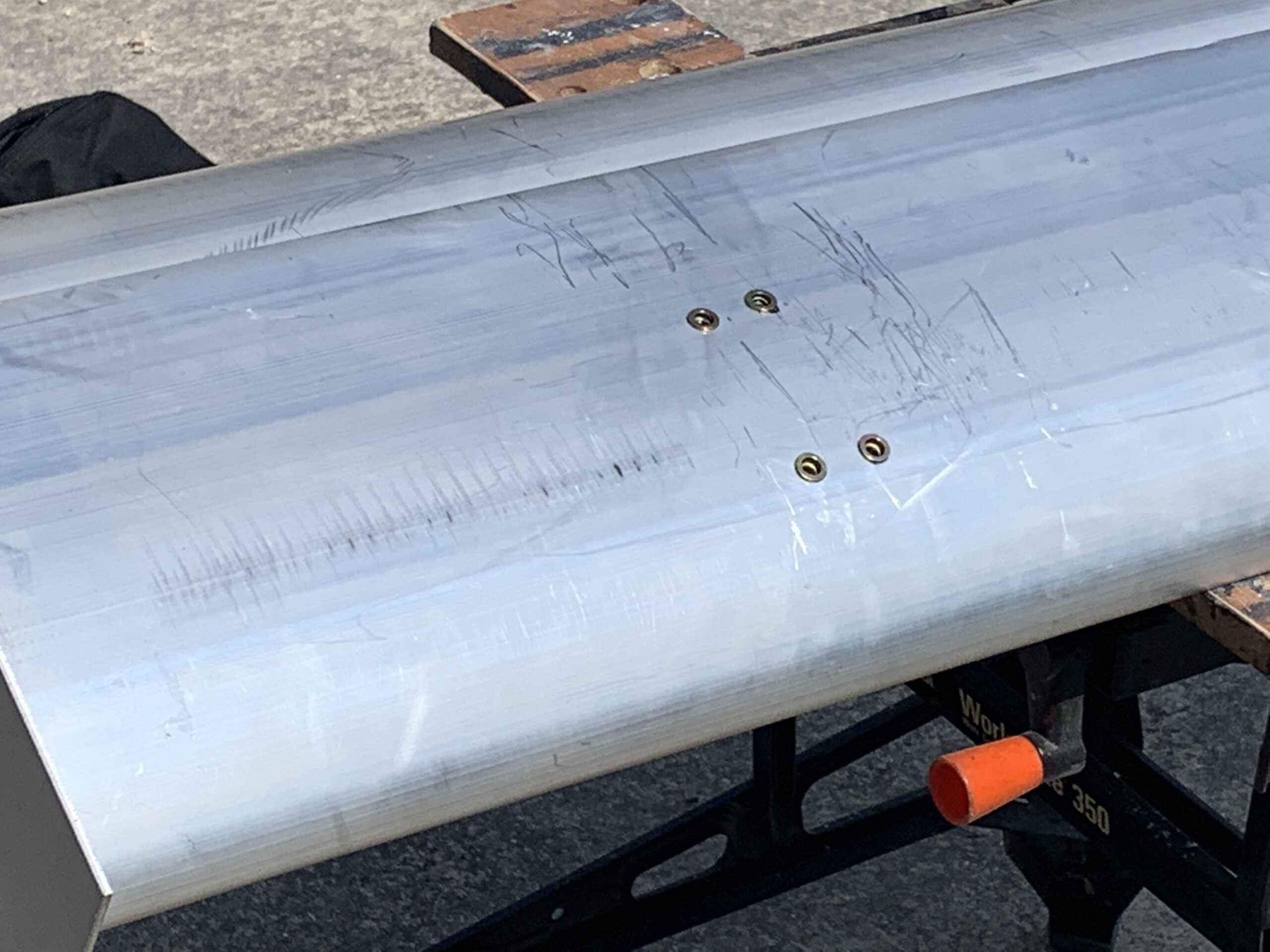
To make the two uprights/end plates, I cut those out of ¼” aluminum. I drew and made more
than 20 full scale patterns until I found the shape that I thought maximized surface area,
adjustability, and didn’t interfere with access to the engine, meet SCCA rules……not easy to do,
still working to perfect it

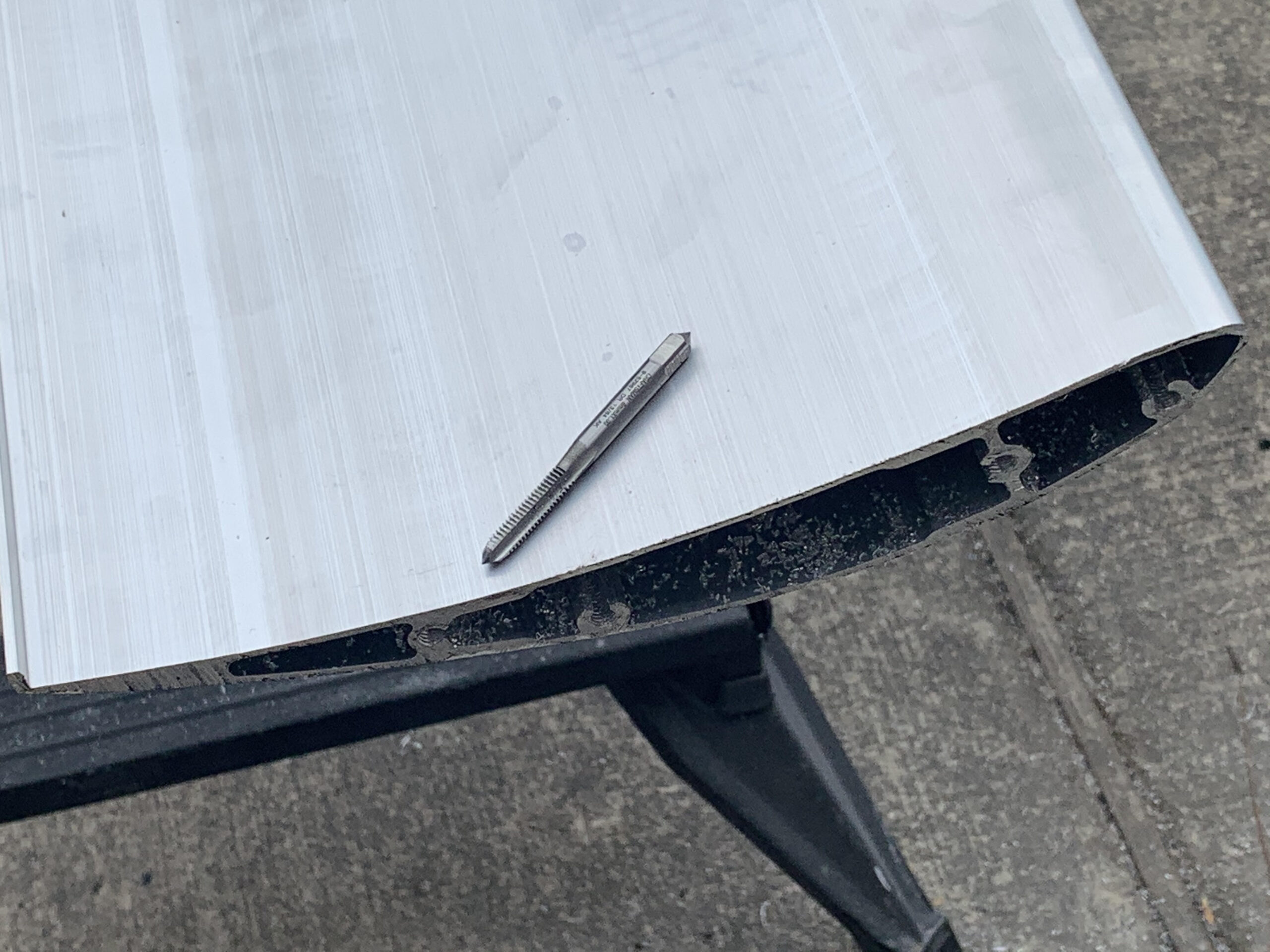
The notches in the bottom of the end plate are to accommodate the new socket head fender
bolts.

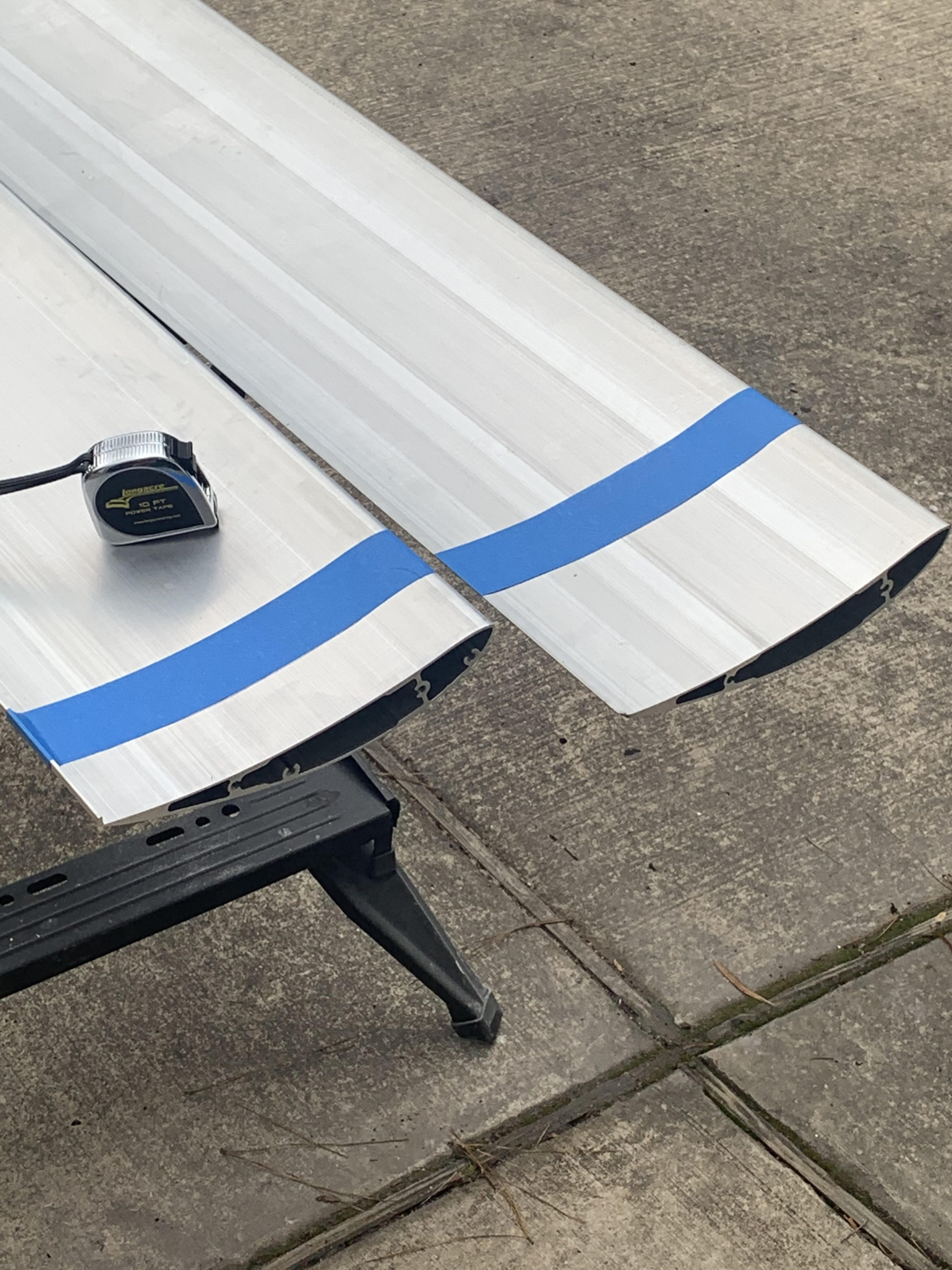
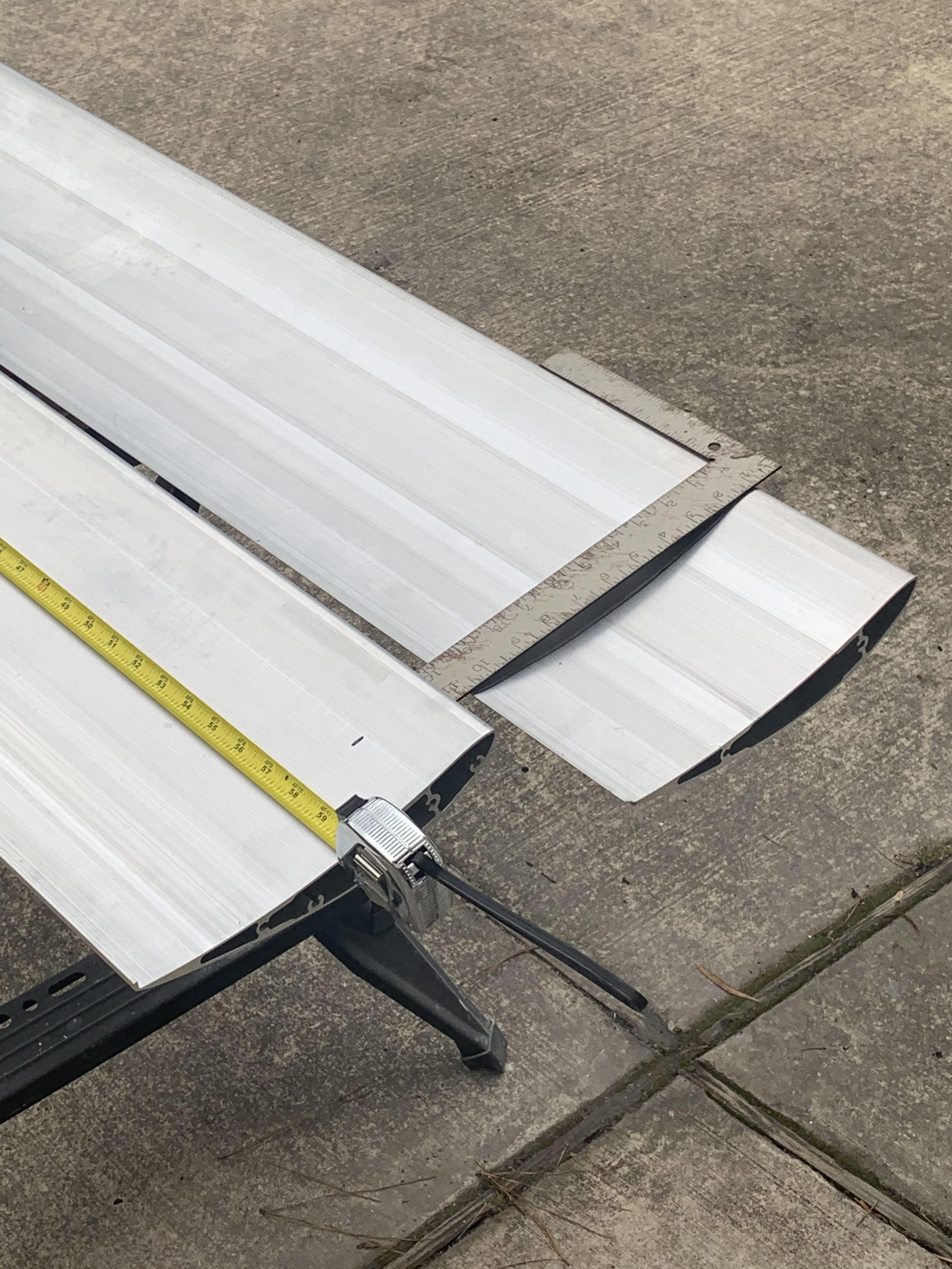
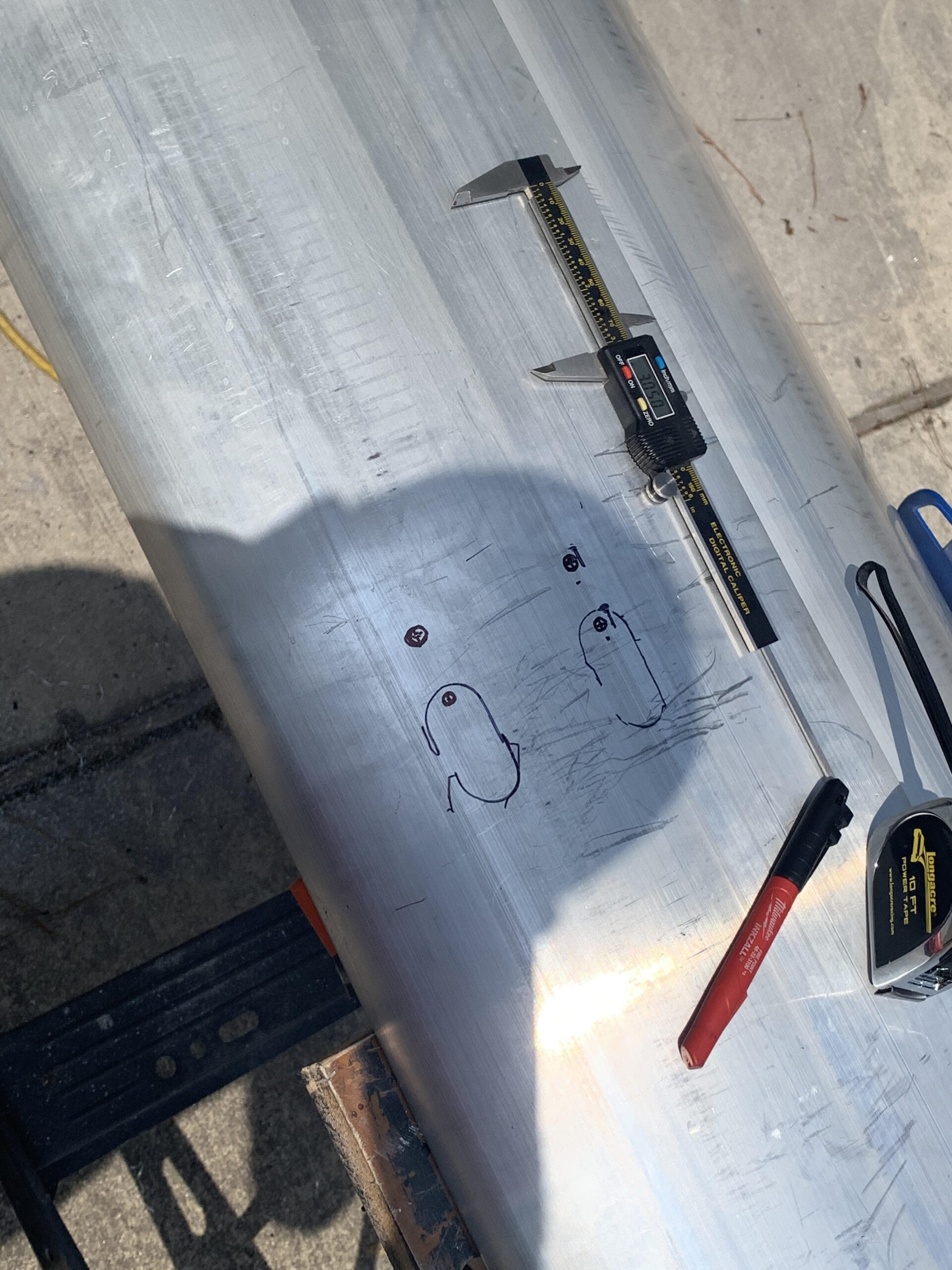
The 2 end plates are 1.7 degrees inward at the rear, so cutting the wing to match, plus being
able to adjust was tricky to say the least.
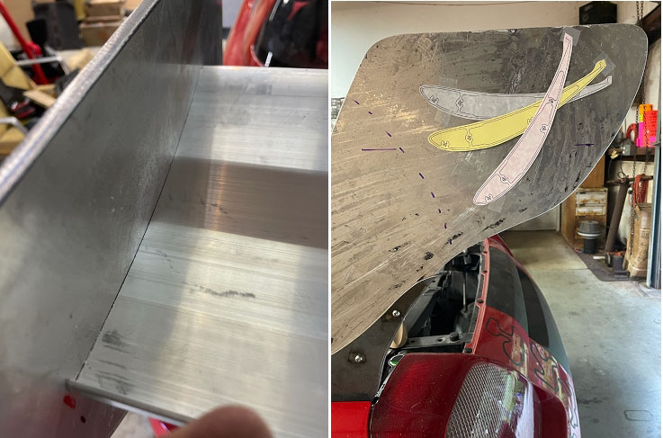
I threaded all 4 holes inside the wing 30mm deep. On the end plates, I drilled holes to have 5,
10, 15, 20, degrees of adjustability. The less degrees for full fast tracks, more degrees for
slower tracks and autocross events for the most rear downforce / drag. The dash line is the
rear engine cover clearance line. I wanted to make sure at any position I could open the back
to make suspension adjustments without having to mess with the wing.
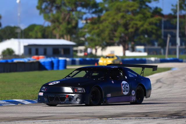
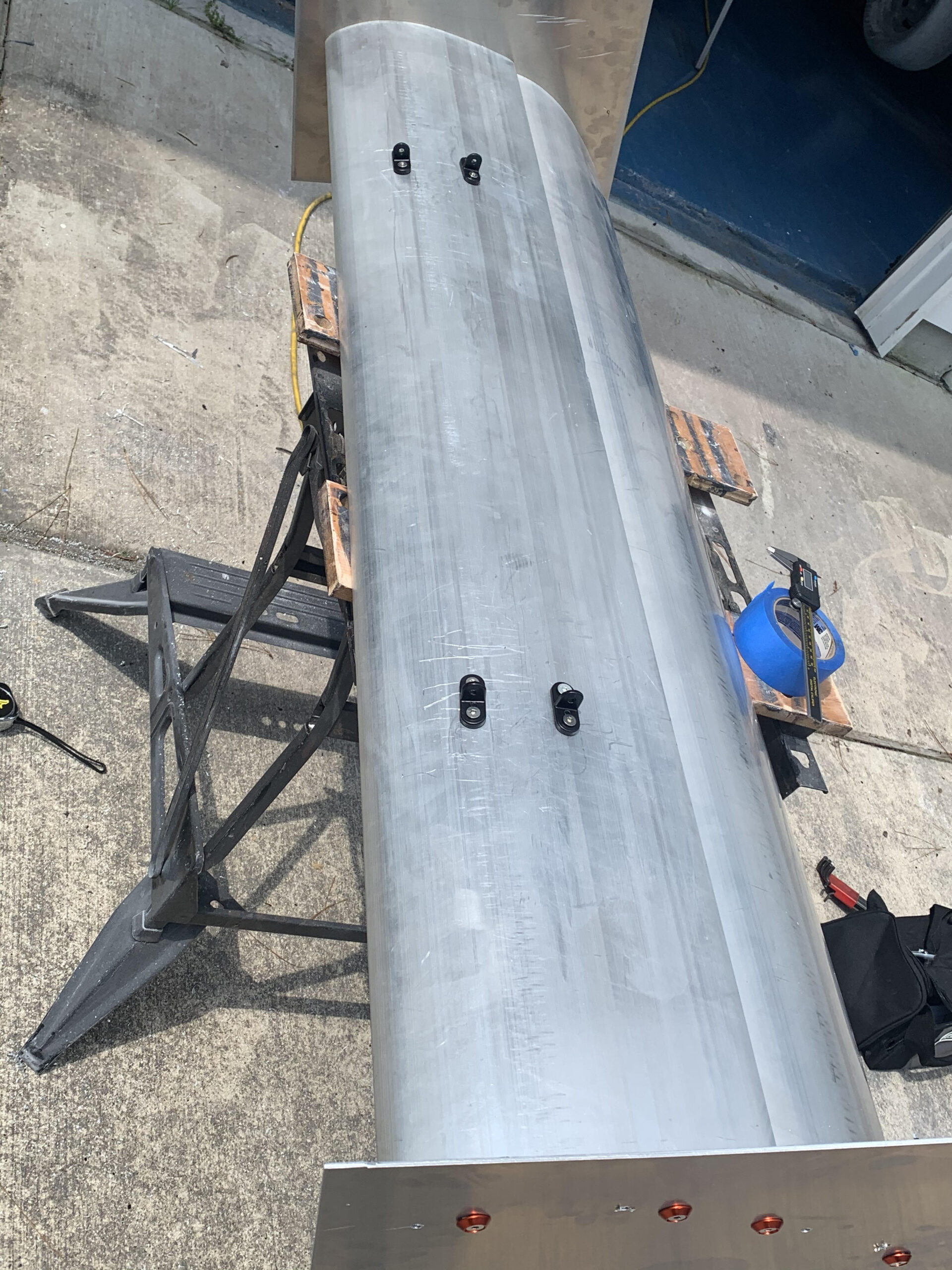
With the steel upright frame extending up and back to match the end plates the overall wing
doesn’t move side to side at all. I used Chicago barrel bolts to connect uprights to end plates to
maximize aerodynamics the best I could. When I finally test everything, the updated package
will include fasteners that will be flush with the entire assembly. In doing so I will be able to
lessen the gap between the frame and the engine cover to help with overall aerodynamics.

Moving forward I plan to make adjustments and bring the wing down a few inches overall.
Sadly, in less than a year the 1ZZ engine let go at MSR Time Trial event on the last lap….sigh
So 10 months later, it now has a used 2ZZ engine with all kinds of upgrades and putting out a
lot more horsepower. On down the line, I hope to add a super charger like the 2ZZ in the Lotus
Elise, or put a turbo on it to bring the horsepower over 350. I have been able to change tire
sizes with 8×15 wheels. I am running 225/45/15 in the front and 245/40/15 in the rear. Once
the engine has been upgraded, the plan is to go 245 front and at least 265+ in the rear.
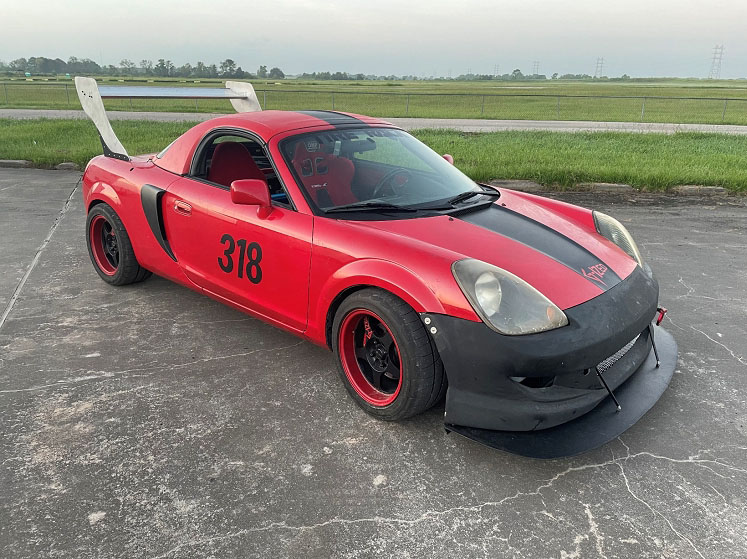
With the new front splitter and wing, first time out on MSR Houston I dropped 11 seconds off
my personal best. The car finally stuck to the track, especially over the “Launch” built into the
track to purposely get the front end of the car light. Previously, I had to lift and touch the
brake over the Launch to make sure the nose of the car stuck. Now for the first time I can go
over the Launch at full speed gaining several seconds in that area alone.
Currently I am working on the final new front end with a new splitter which will include a
combination of canards, fender flares and the splitter will have end fins that will connect the
fender flares to the canards. As for the wing, I have already added more holes for small
adjustments to the upright end plates to better fine tune the wing adjustment to meet each
track and conditions. Stay tuned for more pictures to come……….
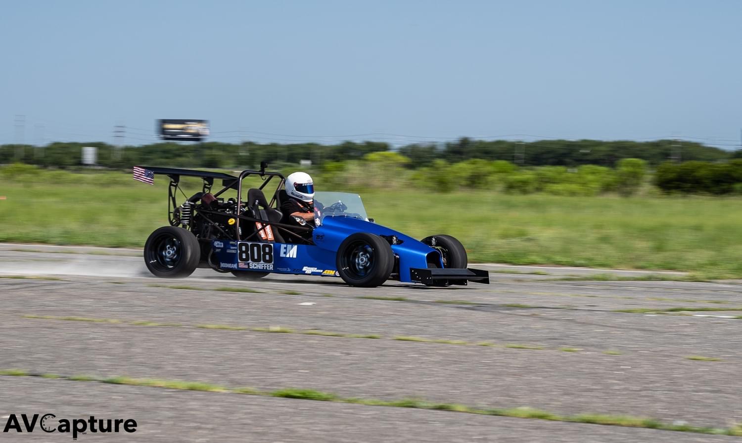
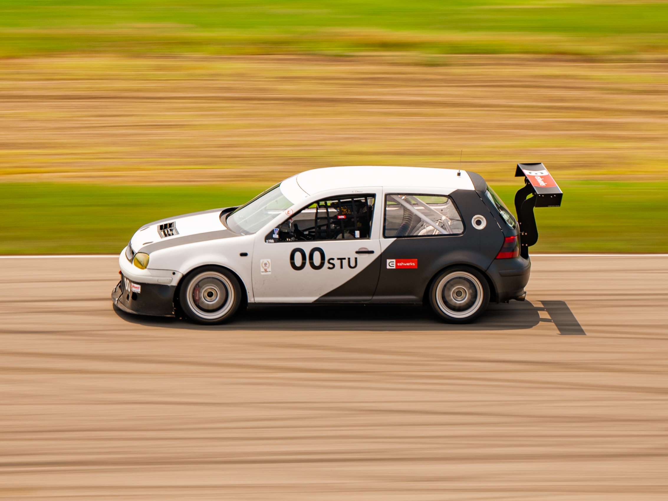
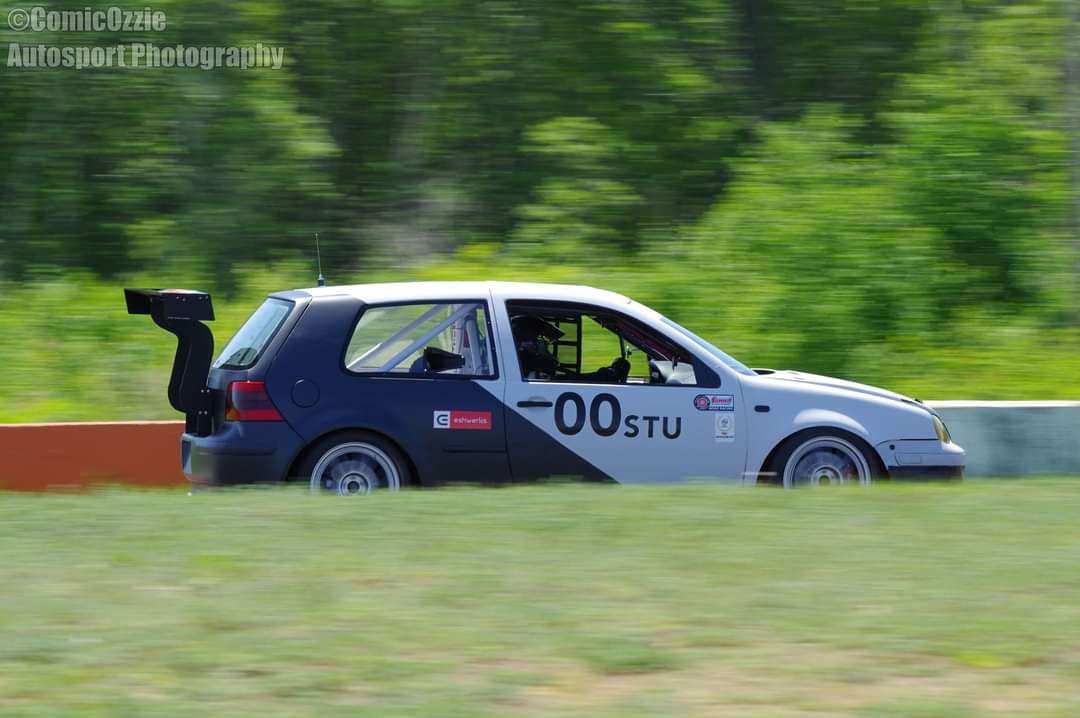
John Shcaeffer – Cleveland/Toledo – ChampCar, Auto Cross, and Track Days

